Overview
This is yosi from Chillout with Beats.
VCV RackThis is the XNUMXth article.
Click here for previous article
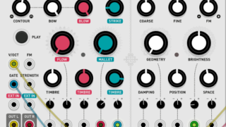
Continuing from the last time, we will introduce recommended modules.
this time too, Mutable Instruments Was the baseAudible Instruments.
Tidal Modulator (Tides)
Tidal ModulatorIs a so-called LFO.However, it is possible to output more complicated waveforms instead of the simple waveforms that come with the standard.
And since it can be easily synchronized with the clock, it is very convenient when working with a sequencer or DAW.
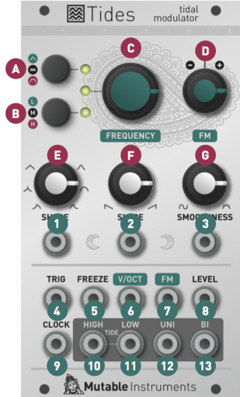
Tidal Modulator points
I will briefly explain only the necessary parts when using it as an LFO.
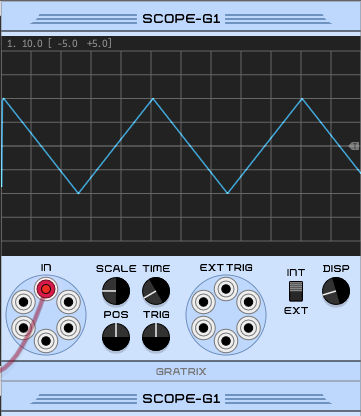
Tidal ModulatorIs unique, so it is better to work while looking at an oscilloscope such as SCOPE.
(If this is an actual machine, do you buy an oscilloscope ... it's just a swamp)
A little derailed, but the oscilloscopeGratrixSCOPE-G1 or standard SCOPE is recommended.
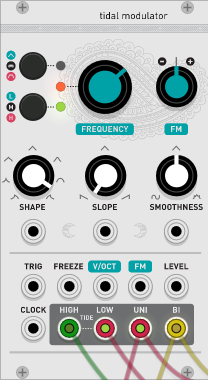
The C knob changes the speed, and the E knob changes the waveform.
The important thing is the exit of the LFO, which is ⑩ to ⑬.
The E, F, and G knobs reflect ⑫ and ⑬.
The difference between ⑫ and ⑬ is the unipolar output and the bipolar output, but in simple terms, it is the difference in the output voltage position.
The explanation of the following site was very easy to understand, so I will quote it.
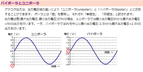
Quote source:Interface Corporation Interface Co., Ltd.
⑫ Unipolar output
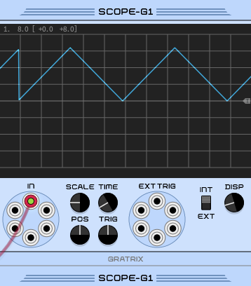
⑬ Bipolar output
Each parameter of Tidal Modulator
A.Mode Switch This button switches between the three modes of operation of Tides: AD Envelope (green LED), Cyclic (LED off), AR Envelope (red LED). To trigger the AD envelope (or AR envelope), a trigger pulse (or gate) must be sent to the TRIG input.
B.Range Switch This button moves between the three frequency ranges of Tides: low (3 minutes to 20 Hz – green LED), medium (5 Hz to 0.05 Hz – LED off), and high (300 Hz to 8 kHz – red). LED). The "high" mode is optimized for audible frequencies, and the shape / slope settings have different response curves optimized for this.Read the "Time Domain vs. Frequency Domain" section for some enlightenment!
C.Principal Frequency Control This knob is in the range of +/- 4 octaves.The output two-color LED next to this knob reflects the amplitude of the generated waveform. The LEDs are green during the attack phase and red during the decay, sustain and release stages.
D. FM input attenuator.This knob controls the polarity and amount of frequency modulation from the FM input (7).If no patch cable is connected to this input, a constant 0.1 V signal is switched internally, so this knob behaves like a fine frequency control.
E.Shape Control This knob adjusts the shape of the wave – it provides different combinations of curvature for the ascending and descending parts.
F.Slope control.This knob balances the rise and fall times.When turned all the way counterclockwise, the rise time becomes zero and the decay segment occupies the entire period of the cycle (decay envelope).When turned completely clockwise, the attack segment takes the full duration of the cycle, and the fall occurs immediately.With the knob at 12 o'clock, the duration of both phases is the same.
G.Smoothness control If set at 12 o'clock, the waveform generated by the wave shaper will be output as is.Turn the knob counterclockwise from 12 o'clock to 7 o'clock to gradually attenuate the high frequency components of the signal (2-pole lowpass filter).Turn the knob clockwise from 12:5 to XNUMX:XNUMX to gradually enrich the high frequency components by folding the waves.
1. 2. 3. CV input for Shape, Slope and Smoothness. The Shape / Slope / Smoothness knob acts as an offset added to these inputs.
4.Gate / trigger input.In cyclic mode, simply sending a pulse to this input resets the phase of the oscillator. In AD and AR modes, this signal is the trigger / gate that drives the envelope.The detection threshold is 0.7V.
5.Freezes the input.Whenever the signal at this input is high, the oscillator or envelope will stop in the track until its input returns to 0V.The detection threshold is 0.7V.
6. V / Oct frequency input.The tide is digital and well tracked.If not, go to the Calibration section to fix this.
7. FM input The signal at this input is attenuated by (D).
8. LEVEL input.This input acts as a VCA for scaling the UNI and BI outputs (input range: 0V-8V – higher voltage allowed and clipped).This input is standardized to a constant 8V signal – if no patch cord is connected to this input, the UNI and BI outputs will have maximum amplitude.
9.Clock input.The oscillator frequency or AD / AR cycle time can be synchronized to an external digital signal (detection threshold 0.7V).See the Clock / PLL Mode section for this.
10.It is a storm surge output.This output goes high (about + 5V) at the end of the attack phase and stays at this level until the cycle resumes or the envelope is retriggered.
11.Output at low tide.This output goes high at the end of the decay / release phase (about + 5V) and stays at this level until the envelope is retriggered.Both high tide and low tide outputs can be used for envelope chains.
12. 13.Unipolar and bipolar outputs.The unipolar output is in the 0V range and the bipolar output is in the +/- 8V range.be careful.These outputs have very different shapes – it's not just a matter of scale and offset – after all, there are CV processor utility modules for getting unipolar waves from bipolar waves, and vice versa.
Clock / PLL mode
To lock the signal frequency to an external clock source, press the range switch (B) for 1 second. The Range LED flashes to indicate that the module is operating in clock / PLL mode.In this mode, the frequency knob no longer controls the frequency of the signal, but instead controls the ratio between the output frequency and the clock input frequency – it allows both clock division and multiplication.
The available ratios are:
1⁄16 ; 1⁄12 ; 1⁄8 ; 1⁄6 ; 1⁄4 ; 1⁄3 ; 1⁄2 ; 3⁄5 ; 2⁄3 ; 3⁄4 ; 4⁄5
1
5⁄4 ; 4⁄3 ; 3⁄2 ; 5⁄3 2; 3; 4; 5; 6; 8; 12: 16
Tidal Modulator Summary
Without looking at the manual at firstTidal ModulatorI didn't understand at all when I used, but I understood it a lot.andAudible InstrumentsAll of our products are really deep.
I think that the person who bought the actual machine will have a lot of trouble in using it in the true sense of the word.
(I don't usually have an oscilloscope)
Comment