Overview
This is yosi from Chillout with Beats.
VCV RackThis is the XNUMXth article.
Click here for previous article
this time too, Mutable Instruments Was the baseAudible Instruments.
Quad VC-polarizer (Blinds)
Contrary to what it looks like this time?It was pretty simple. (Simple and usable is another problem)
First, the official explanation
The blind is a 4-channel voltage control signal modulator.Each channel consists of a polarizing element circuit, also known as a 4-quadrant multiplier.This circuit behaves like a VCA, except that the negative control voltage inverts the output signal rather than silence it.The blind outputs are daisy-chained, so you can mix groups of all adjacent 2, 3, or 4 channels.
I'm not sure if Google's translation accuracy isn't very good or what he's saying.
It looks like a 4-channel electro-optic voltage controller.
It seems to be similar to VCA, but it seems to behave differently when it is negative.
Signal flow
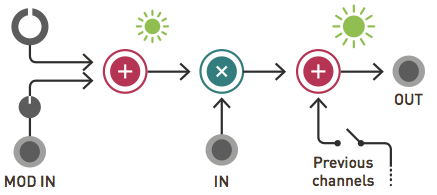
The signal input from IN will be modulated here if MOD IN is input.
The Previous Channels then mix the signals of the previous channel.
I haven't seen this area.
Key Points
I hadn't even searched for it until now, but CLOCK FACE MODULAR STORE gave a very good explanation.
I will explain it with figures while also referring to this.
There are three patch examples, so let's take a closer look.
Bipolar LFO → Unipolar LFO
I will quote the explanation of CLOCK FACE MODULAR STORE.
Instead of patching the signal input, patch a negative (+ bipolar) LFO that moves from positive to positive to the modulation input. If you raise the gain knob fully to the right and Attenuverter to the right, you can convert it to an LFO that moves only in the positive range (unipolar).
You can adjust the plus and minus swings of the LFO.
(It may be better not to do it with an actual machine)
In the following conditions, the LFO swing width is the same for both plus and minus.
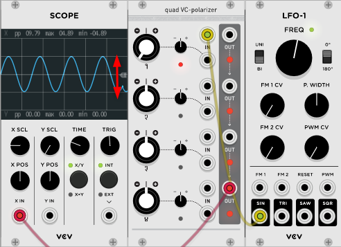
If you move the second A knob in the minus direction, the sine wave will move only in the minus direction.
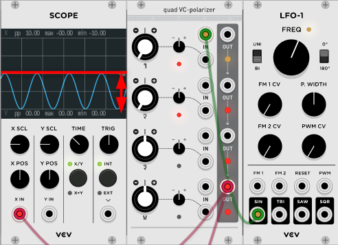
In the explanation of CLOCK FACE MODULAR STORE, it was a method to put in the modulation input, but the same thing could be done with the above method.
Cross fader
This is a way to crossfade the two inputs.
I will quote the explanation of CLOCK FACE MODULAR STORE.
Put the first of the signals you want to crossfade into the CH1 signal input and the second into the CH1 signal input. Set the gain knob to the same position for CH 2 and CH 2 on the right side. The CV used for crossfade is branched by multiples and patched to the CH1 and CH2 modulation inputs (same CV input for 1 channels). Set Attenuverter on the positive side for CH2 and on the negative side for CH2 to the same level. Extract the signal from the CH 1 output.
When applied to the oscillator, it changes like a wobble base.
You may be able to use it if you sync it with BPM.
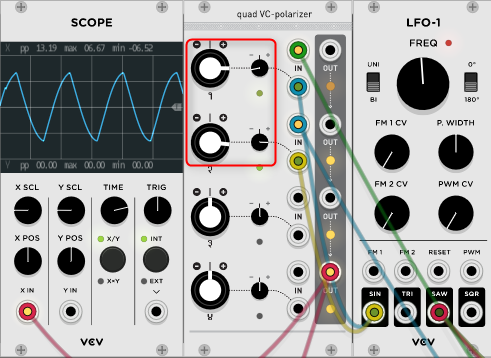
Set the A knob to 3 o'clock and the B knob to 9 o'clock and 3 o'clock, respectively.
In the example below, the sine wave is put into the first input and the SAW is put into the second input.
The modulation is the same for the first and second sine waves.
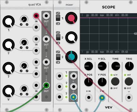
I don't know if it's an image, but on the Scope, the sign and SAW wave crossfade and switch at the LFO cycle.
Ring modulator
I will quote the explanation of CLOCK FACE MODULAR STORE.
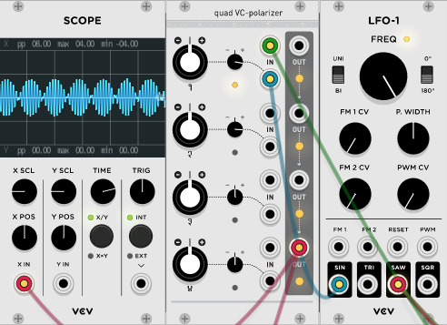
Input the two audio signals you want to mix into the signal input and modulation input. Move Attenuverter from the center to the right to apply ring modulation. If you move the gain knob from 2 o'clock, the original sound to the signal input will be mixed with the output.
This is easy, isn't it?
The point is that the higher the frequency, the more like a ring modulator.
CONTROLS, INPUTS AND OUTPUTS
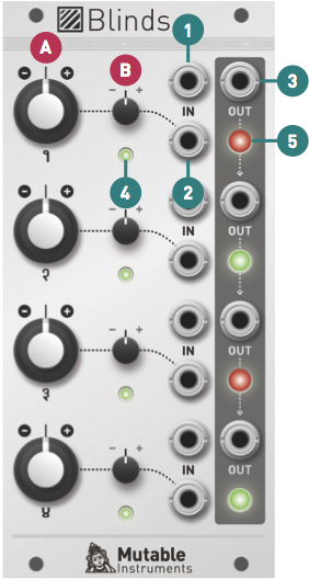
A.Channel polarity and gain. At 12 o'clock, the channel will be muted.Turning it clockwise amplifies it, and turning it counterclockwise amplifies it and inverts it.
B.Modulation attenuator.Adjusts the amount and polarity of the modulation from the modulation input (2), that is, the amount and polarity of the channel polarity and gain that fluctuate around the center value set in A.
1.Signal input.The blind input is DC coupled and accepts both audio and CV signals.If no patch cable is inserted, this input will be supplied with + 5V.
2.Modulation input.This input is also DC coupled.Blinds acts as a pure ring modulator when the audio input signal is on both the signal input and the modulation input.
3.Signal output.If the patch cable is not connected to the output, the signal from this channel will be routed to the next channel.For example, if the patch cable is not patched to output 1, output 2 will contain the sum of channel 2 and channel 1.If outputs 1, 2, and 3 are unpatched, output 4 contains the sum of all four channels.
4.Gain and polarity indicators.Color corresponds to polarity (green = positive, red = negative), and brightness corresponds to gain.
5.Output level and polarity indicators.
Summary
CLOCK FACE MODULAR STORE's explanation is very easy to understand, and I regret why I didn't find it earlier.
I will rewrite past articles and write patch examples to make it easier to understand.
(What kind of blog was this blog ...)
Comment