Overview
This is yosi from Chillout with Beats.
VCV RackThis is the XNUMXth article.
this time too, Mutable Instruments Was the baseAudible Instruments.
Audible InstrumentsAll of the modules are cool, but it's too difficult!
I think of it, the sad face of a person who bought hardware just by the momentum ...
The manual is in English, I have a small amount of modules, there is no sound ...
(One module is roughly2-6)
I am writing an article with a strange sense of duty to explain the points that can be fun by making sounds to save such people.
I'm affirming that anyone who wants to get started with modular synths should touch the software once.
Click here for previous article
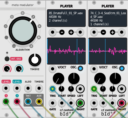
This is the sound made with this Meta Modulator.
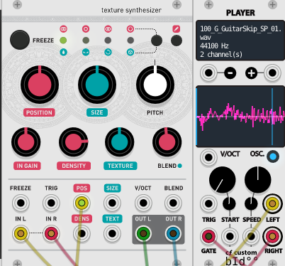
Modulate drum beats from internal oscillators and players for automationAI moved the knob in the automation and recorded with Edison in FL Studio.
Meta Modulator (Warps)
The introduction has become longer, but it's hard to tell if it's a synth in the first place.
Simply put, it feels like a Vocoder.
It modulates the two inputs with various algorithms.
Key Points
The simplest way to use it⑤と⑥Enter different audio in.
⑦Connect to Audio Out and now⑤と⑥ AModulation is applied by a different algorithm depending on the position of.This alone is a lot of fun.
Player is useful for playing a little sample.
Each parameter
I will use the official image.
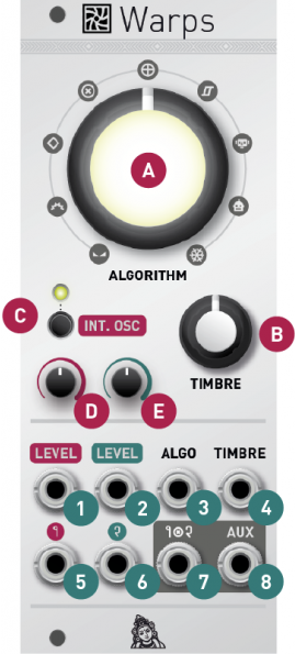
CONTROLS, INPUTS AND OUTPUTS
A. Modulation Algorithm This knob selects whether to perform signal processing operations on carriers or modulators.The algorithm is described in detail in the next section.
B. Modulation Tone This knob controls the intensity of the harmonics produced by cross-modulation – or provides another dimension of tone control for some algorithms.
C. Internal oscillator state.This button enables the internal oscillator and selects its waveform. The LED color depends on the oscillator waveform. When the LED is off, the internal oscillator is disabled and the external signal is used as the carrier.
D. External carrier amplitude or internal oscillator frequency.When an external carrier is in use (that is, when the internal oscillator is off), this knob controls the amplitude of the carrier, or the amount of amplitude modulation from the LEVEL CV input on channel 1.When the built-in oscillator is active, this knob controls the frequency.
E.Modulator amplitude.This knob controls the amplitude of the modulator, or the amount of amplitude modulation from the LEVEL CV input on channel 2.Gains in excess of 1.0 can be applied for a warm overdrive effect.
1. External carrier amplitude or internal oscillator frequency CV input.When the internal oscillator is turned off, this CV input controls the gain of the carrier input.When the internal oscillator is enabled, it instead acts as a V / Oct control of the oscillator frequency.
2. Modulator amplitude CV input.This CV input controls the gain of the modulator input.As with the corresponding carriers, it is internally normalized to a constant + 5V power supply when the patch cable is not plugged in.
3. CV input for the algorithm.The CV for this input is added to the position of the Modulation Algorithm Knob (A).
4. Timbre's CV input.The CV for this input is added to the position of the modulation timbre knob (B).
5. 6. Carrier (1) and modulator (2) audio inputs.Warp expects modular level signals (usually 10Vpp, up to 20Vpp).
7. Modulator output (1x2).This is the main audio output.
Modulation algorithm
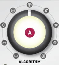
I will explain in order from the left (Google teacher).
cross fade
Carriers and modulators crossfade each other using the constant power law. TIMBRE controls the position of the crossfade – both signals are mixed equally at 12 o'clock.
Cross folding
The carriers and modulators are summed, a small cross-modulation product is added to spice up, and the resulting signal is sent to the wave folder, the amount of which is controlled by TIMBRE.
Diode ring modulation
The carrier and modulator are roughly multiplied using the digital model of the diode ring modulator. TIMBRE post-processes the resulting signal with a variable amount of gain (and emulated diode clipping).
Digital ring modulation
A milder version of the previous algorithm that uses proper multiplication in the digital domain.This is similar to all AD633 based analog ring modulators. TIMBRE post-processes the signal with gain boost and soft clipping.
XOR modulation
Both the carrier and the modulator are converted to 16-bit integers, and the resulting two numbers are XORed bit by bit. TIMBRE controls which bits are XORed.
Comparison and correction
A small number of signals are combined by a comparative operation ("Replace the negative part of the carrier signal with a modulator", "If the absolute value of the carrier is greater than the absolute value of the modulator, the modulator outputs the carrier") TIMBRE Morph through these signals (some of which have an octave pedal flavor).
vocoder
A classic implementation of an analog vocoder with 20 analytical banks and 20 synthetic 3-octave 48dB filters.The modulator subband signal is processed by the envelope follower from which the gain of each carrier subband signal is derived. TIMBRE distorts the relationship between the modulator's envelope followers and the carrier's gain element.Effectively shifts up or down the formants extracted from the modulator signal.
INTERNAL OSCILLATOR
CPress the INT.OSC button in to enable the internal oscillator.Each time you press it, the oscillator waveform is selected. (3 types)
When the internal oscillator is enabledDと①Will be able to manipulate the frequency of the internal oscillator.
I will use the image of the head family as it is.
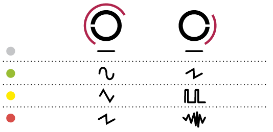
The internal oscillatorAThe waveform changes depending on the position of.
As shown in the figure below, the LED is greenAThe waveform changes depending on the position of the knob.
It changes from 7:2 to 2:5 and from XNUMX:XNUMX to XNUMX:XNUMX.
When the LED is green: sine wave, sawtooth wave
When LED is yellow: Triangle wave, pulse wave
When the LED is red: sawtooth wave, noise (low-passed)
Summary
I've written it so many times that I think it's the first time, but it's hard to understand.
(Why doesn't the internal oscillator switch at 12 o'clock ...)
However, there is no doubt that it can produce sounds that ordinary soft synths cannot produce.
And because of the high degree of freedom, the range of ideas expands.
It's no wonder that modular synths are popular as presets are becoming mainstream.
Comment