Explanation of Voltage Modular BOOLEAN LOGIC
This is yosi from Chillout with Beats.
I'm going in a slightly maniac direction, but it makes a big difference later depending on whether or not I have a solid understanding of this area.
First is the Google Translate of the manual.
Google Translate of BOOLEAN LOGIC Manual
A Boolean logic module is a dual module that combines two input gate signals using the common Boolean functions AND, NAND, NOR, OR, XOR, and XNOR.
Each function creates a different gate signal output based on the state of the two input signals. Using only one input gives the same result as when combined with a second input that is always "off".The signal is considered "on" when the voltage is above 2V and "off" when the voltage is below 1V.The result of each function is based on the rules that define it.
- AND Outputs the gate signal only if both inputs are "on".
- OR If either of the two inputs is "on", the gate signal is output.
- XOR (exclusive OR) Outputs the gate when only one of the inputs is "on", not both.
The N (not) version of each function produces the same gated signal that is just inverted.

It's called a gate signal, but it also works with LFOs and oscillators.
Illustrate AND, OR, XOR.
AND
AND outputs the Gate signal "only if both inputs are" on "".
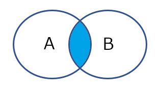
NAND
N (Not) reverses the operation.In short, if there is no input, the Gate signal will continue to be output.
In NAND, the output of the Gate signal stops when both are input.The point is both inputs.One of the inputs will continue to output the Gate signal.
OR
Since OR is "when either of the two inputs is" on "", if either of them comes in, the Gate signal will be output.
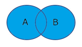
NOR
N (Not) reverses the operation.In short, if there is no input, the Gate signal will continue to be output.
In the case of NOR, the output of the Gate signal will stop if there is one input.Both inputs remain unchanged and the Gate signal continues to stop.
XOR
"The gate is output when only one is" on "", so if there is an input on one side, the Gate signal will be output.If both come in, the Gate signal will be stopped.
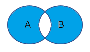
XNOR
N (Not) reverses the operation.The Gate signal is stopped only when only one is off.If both are input, the Gate signal is output.
Example of usage
AND usage example
I will change the patch of the Kick drum made in the previous article.
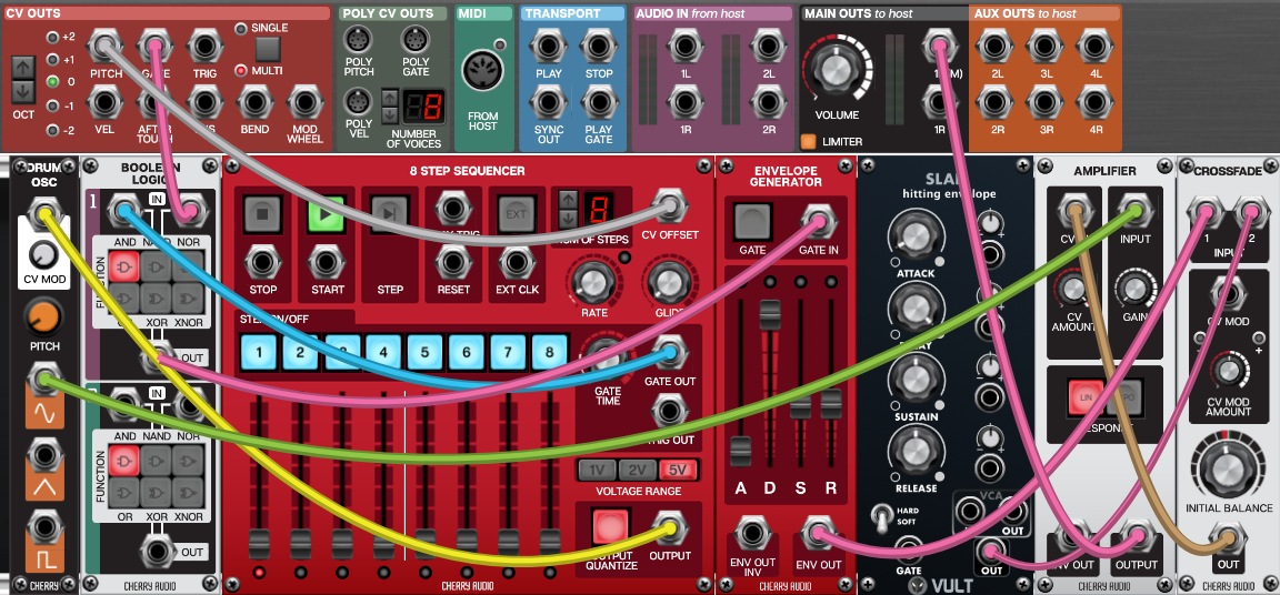
The following example uses the AND function to combine the gate output signal from the running sequencer with the gate signal from the keyboard to output the sequencer gate pattern only while the key is pressed.
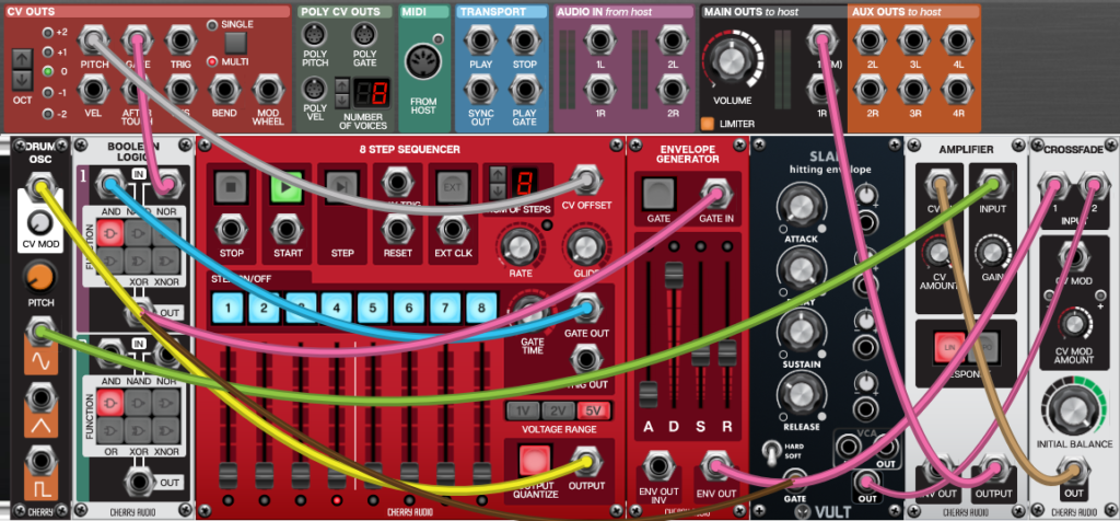

To briefly explain, "AND" isGATE signal is output from OUT1 only when signals are input from both IN2 and INXNUMX.Will be
With the above settings, the GATE signal is periodically input from IN2, but the gate signal is not input to IN1 unless the keyboard is pressed.
Therefore, while the keyboard is pressed, it is output at the timing when the GATE signal from the sequencer enters IN2.
Example of using OR and XNOR
In this example, the gate signal from the CV Outs section of the I / O panel is patched to one of the inputs of both modules.The upper module function is set to OR and the lower module is set to XNOR.With this setting, the sequencer starts when a key is pressed and stops as soon as all keys are released.
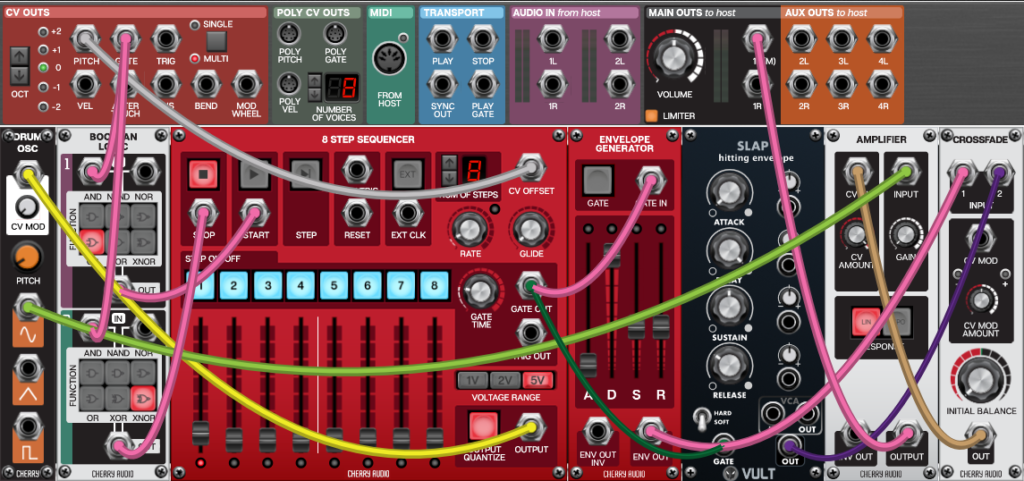

This is an example of using the fact that OR and XNOR move in completely opposite directions.
OR outputs a GATE signal if a signal comes in on one side.
Summary of explanation of Voltage Modular BOOLEAN LOGIC
The idea of BOOLEAN LOGIC itself is common, so it's worth remembering.
To be honest, I'm tired of Ignite, so I will move to Core from the next time.
![[Free] Reverb Drum Machines | The Complete Collection is free for a limited time! 20 2019 08 23 23x54 08](https://chilloutwithbeats.com/wp-content/uploads/2019/08/2019-08-23_23h54_08.png)

Comment