Overview
This is yosi from Chillout with Beats.
VCV RackThis is the fifteenth article.
Click here for previous article
I have to prepare a summary page soon.
Continuing from the last time, we will introduce recommended modules.
this time too, Mutable Instruments Was the baseAudible Instruments.
Mixer (Shades)
It's simple, but it doesn't work as expected!
I want you to improve usability a little more.

Key Points
A.The switch is onBThe knob of is 12 at 0 o'clock, and it becomes 1 by swinging left and right.It is flipped on the left and right.
It looks like the following.
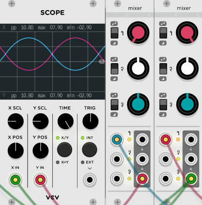
A.The switch of is the same as a normal mixer at the bottom, 0 when it is swung all the way to the left, and 1 when it is right.
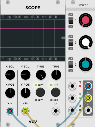
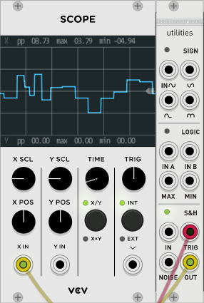
What is different from a normal mixerA.When the switch is up,1.With the cable not stuck inBIf you shake it all the way to the left and right, it will continue to output + -5V.BIs 0 in the middle.
A straight line, not a curved line like an LFO, seems to be useful. (I wish MIDI CC was assigned to the knob)
2.Behaves a little strangely.
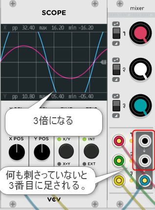
2.If the three channels of are linked and the cable is not stuck in the OUT, it will be routed to the next OUT.that's why,2.If the cable is stuck only at the bottom of, you will hear the sound of the top two channels added.
It's hard to understand if it's a word, so I'll post an image.
CONTROLS, INPUTS AND OUTPUTS
A.Function Selector This control sets the channel as an attenuator (lower position) or attenuator (upper position).
B.If the gain channel is set as a participant, the gain range is 0 to 1.Turning the knob all the way counterclockwise mutes the signal, and turning the knob all the way clockwise passes it unattenuated.
If the channel is set as an attenuator, the gain will be in the range -1 to +1.Turn the knob all the way counterclockwise to invert the signal, and turn it all the way clockwise to pass without attenuation.Setting this knob to 12 o'clock will mute the signal.
1.Signal input.When nothing is patched to this input, a constant voltage of + 5V (or + 10V) is sent to the attenuator / attenuator.Therefore, a constant voltage of adjustable level and polarity is produced at the output.The three jumpers on the back of the module select the voltage to be sent to each of the three inputs + 3V, + 5V, or + 10V (if the jumpers are removed).
2.If the signal output patch cable is not connected to the output, the signal from this channel will be routed to the next channel.For example, if the patch cable is not patched to output 1, output 2 will contain the sum of channel 2 and channel 1.If outputs 1 and 2 are unpatched, output 3 contains the sum of all three channels.
Summary
I wonder why the sound gets louder if I don't know how to use it properly.
When I touch it, I realize that it is a very usable module.
It is around this time that I will read the manual again.
Comment