Overview
This is yosi from Chillout with Beats.
VCV RackThis is the XNUMXth article.
Click here for previous article
Continuing from the last time, we will introduce recommended modules.
this time too, Mutable Instruments Was the baseAudible Instruments.
I will go smoothly.
Utilities (Kinks)
The theory is simple this time as well, but I wonder if there are many uses.
SIGN SECTION
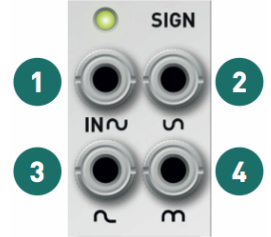
1.input
2.Inverted output.Besides the typical CV application (reversing the direction of the envelope or LFO), the inverter helps to create interesting waveforms from the VCO output.For example, invert the sinusoidal output of a traditional analog VCO and mix it with the sawtooth (or triangular) output.This is the same as attenuating the fundamental frequency of the sawtooth (or triangle) waveform to create a sound closer to the nose.
3.Half-wave rectified output.The negative half of the signal is clipped to 0V.It can add many overtones to the audio signal.
4.Full-wave rectified output.The negative half of the signal is inverted.For symmetric waveforms such as sine and triangle waves, this doubles the frequency of the signal (the "octaver" effect).Another interesting application is to preprocess a random signal before sending it to a quantizer or digital VCO.Some of these do not handle negative CVs.
The monitoring LED shows the amplitude and polarity of the input signal.
Key Points
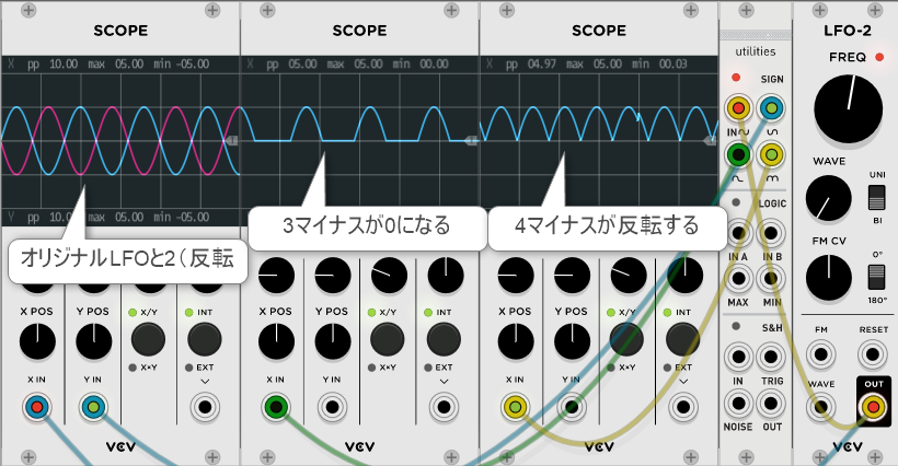
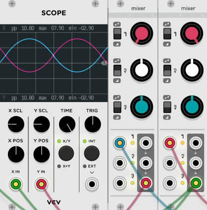
It's hard to understand if it's just words, so I prepared an image.
These are the results of inputting LFOs (sine waves).
On the far left is the original LFO2.is.It's flipped, so it's just the opposite.
LOGIC SECTION
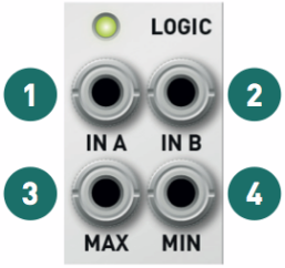
Remember how logical OR gates work. Whenever one of the two inputs is at a high level, its output is at a high level (for example, + 2V).This rule can be expressed in another way.The output is the maximum of the two inputs.This is exactly what an analog OR circuit (also known as a max or peak circuit) does. Takes the maximum of the two input voltages.If these voltages are digital signals (for example, low level 1V and high level 5V), this circuit behaves like a digital OR gate.
1.,2.Normalized signal input to.
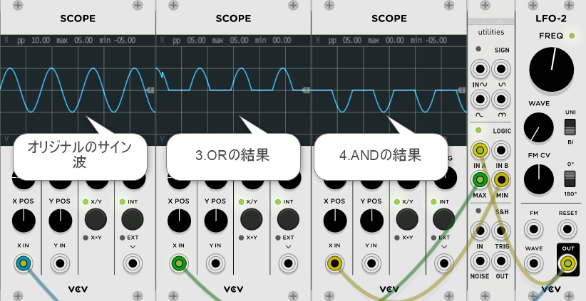
3.Analog OR signal (maximum, peak).
4.Analog AND signal (minimum, valley).The monitoring LED shows the total amplitude and polarity of the two input signals.There are some interesting findings.
The inputs are normalized to 0V, so if you patch the cable to only one input, MAX will output the positive half of the waveform and MIN will output the negative half of the waveform.
Of course you can use these to manipulate digital triggers, gates, or clocks.
For audio rate signals, the resulting waveform has the same kind of anharmonic subtones and sidebands that can be obtained with a ring modulator.
The classic "Buchlaesque" application is to combine different AD envelopes or triangle LFOs to create very complex shapes.
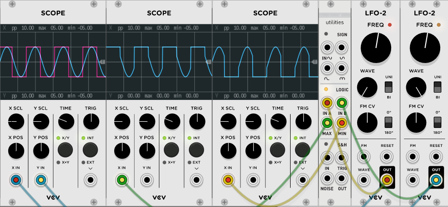
Another interesting patch is to use a slow LFO to clip a triangle or sine wave.This produces a PWM-like effect.
Key Points
It's hard to understand that this is just words, so I prepared an image.
LFO (sine wave)INAIt is the result of inputting only to.
LFO (sine wave)INA,LFO (square wave)INBIt is the result of inputting only to.
S & H AND NOISE SECTION
Each time a trigger is received on the TRIG input, the output voltage takes the value of the input voltage and holds this voltage until a new trigger is received on the TRIG input.
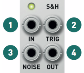
1.Normalized signal input to the white noise generator.
2.Trigger Input Requires a signal with a sharp rising edge (clock / gate / trigger generator, square LFO or VCO).
3.Noise generator output
4.Sampling and holding the output.
The monitoring LED shows the amplitude and polarity of the output signal.
It is important that the trigger input signal has a sharp rising edge.The module is sensitive to the slope of the signal, not its value. It is not possible to use slow signs or triangle LFOs to trigger S & H (of course such signals can be sampled through the IN input and turn them into crazy stairs).The trigger signal can be up to 10kHz. Try patching a high-pitch square VCO to the TRIG input to add aliasing to the audio signal sent to the IN ("bit crash").
Since this circuit is analog, the output voltage cannot be held indefinitely.The output voltage decreases very slowly towards 0.8 at a rate of less than 1 mV (0 cent) per second.
Sending a clock or trigger to the TRIG input without the signal patched to the IN input produces a stepped random signal.The output level is adjusted so that the output value is between -2V and + 2V for more than half the time.Very rarely, it is below -5V or above + 5V.
The NOISE output can be used independently of the S & H circuit.
Key Points
This is a pretty maniac guy.
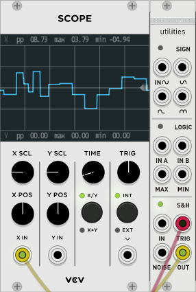
1.You can output a sequence by inserting an LFO etc. and inserting a trigger in 2.
2.When you enter a trigger, at that trigger timingINThe value of the input voltage of is output from 4.
With trigger timing and input value4.The output of is determined, and it keeps holding until the next trigger is input. (In the case of analog circuits, it seems that it gradually goes to 0, but since it is digital, it does not seem to operate like that.)
Also, if you input a trigger with nothing connected to IN, a random signal will be generated.
It can be used when you want a random signal.
Summary
If you're modular and different, you'll want different LFOs.Especially the pattern that the minus part is 0 in the sine wave.
It's good that it's easy to make.
It is also wonderful that white noise can be output.
Utilities is pretty plain, but it's a really usable guy.

Comment